Understand your own sound system
Reflections in your room across spectrum
- RT60
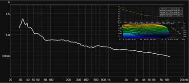
RT60 is a pretty straightforward measurement for showing how fast the sound decays in 60 decibels across the spectrum. The longer time of decay means the sound stays longer in the room or site by being trapped inside with reflective surfaces. Normally, we would see a relatively short RT60 from high frequency (HF) to middle frequency (MF) and a sudden pop-up to long time (over a second) in the region from upper low frequency (LF) to the low end bottom. This happens because the HF/MF are much easier to be absorbed by the acoustic materials than the LF. And adding the factors of the narrow directivity of HF/MF and their wavelength nature, the HF/MF we mostly hear in the room are the direct sounds, as our human hearing system is easily able to separate them from the reflections. Contrary, the LF has been significantly boosted and typically merged with its own reflections, where the artifacts of summations are not aligned with our perception due to the analytic mechanism differences between ears and machines. The long wavelength (e.g., 17 meters@20Hz) of the LF is very hard to absorb by the materials (not cheap either), and their sum leads to the drastic amplitude and phase shift. That is why people often say the bass sound is usually non-directional. But truthfully speaking, they are actually omnidirectional and can easily be masked its source direction by the reverberations. This would be better to explain this behavior of sound summation by the Wavelet Transform.
How the reflections alternating the magnitude and phase
- Wavelets (IR across spectrum)
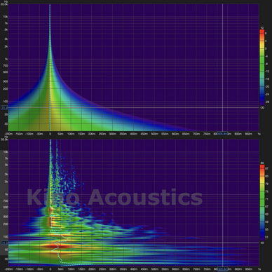
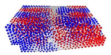
Wavelet Transform analyzes the audio signal to provide the energy distribution details over both time and frequency simultaneously. We can see it as an Impulse Response (IR - ideal short input over time) but also across different frequency bands. The picture at the top is the Wavelet Transform of a perfect audio signal with the Flat frequency/Phase response. From Top to Bottom (y-axis), we can see a vertical frequency response where lower positions correspond to lower frequencies (stretched impulse/wavelets) and higher positions to higher frequencies (compressed impulse/wavelets). The picture at the bottom is the Wavelet Transform of the direct/reflected summation sound. The ripples on the right of the main trunk are the reflections from all the reflective surfaces. Some reflections we might not see here are the early reflections that have merged with the direct sound (main trunk) and show different kinds of artifacts, such as comb filtering and phase shift. Wavelet Transform is a great tool to identify time/frequency domain anomalies.
Sweet spot identification
Inter-channel Sound pressure level (SPL) balance
- Frequency/Phase Response (with specific FTW)
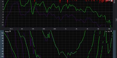
Frequency(Magnitude) and phase response are the most basic real-time analyses for audio signals. They utilize the Fast-Fourier Transform(FFT) method to provide the details of sound wave intensity across the hearing frequency spectrum and timing relationship between different frequency bands, measured in phase degrees. In frequency response, we utilize the dual-channel FFT with a specific Fast-Time Windowing (FTW) to measure more accurate magnitude by cutting out the lateral-arrive reflections. In phase response, although it’s not as intuitive as the frequency response, it is a very powerful tool for phase/time alignment, as its real-time feature and very easy to identify the phase relationship broke-up. But in terms of the alternation by reflections, the Wavelet Transform would be better suited for the insights.
Inter-channel Sound pressure level (SPL) balance
Inter-channel Sound pressure level (SPL) balance
Inter-channel Sound pressure level (SPL) balance
- Don't measure in C-weighting
To maintain Sonic Image perfectly intact, the SPL between channels must be perceptually identical or at the same reference level as the standard required. However, due to the fact that the environment (room) response alters the direct sound sufficiently, the frequency response would not be flat and should not be equalized to be flat unless it is in the anechoic condition. On top of that, the SPL meter (C-weighting) measurement will not be aligned to our loudness perception, especially in LF, as the meter is measuring the accumulated acoustic energy, which has a wide range of variation in decibels. A very high chance of deviation in loudness perception unless you flatten the steady-state response. Otherwise, SPL balancing in multiple channels would be really challenging in high sound quality systems. The highest priority is to get the perceptual frequency response identical or as close as possible, where only the ear tuning approaches like the “Timbre Chart Method” could achieve this accuracy.
Room Mode (for Subwoofer Array Design)
Inter-channel Sound pressure level (SPL) balance
Room Mode (for Subwoofer Array Design)
- Identify the Nodes
Room modes are low-frequency (LF) resonances caused by specific frequencies matching the room's dimensions, which create standing waves that result in peaks and dips in the sound. As the LF acoustic treatments are expensive, room modes are a major challenge for accurate sound reproduction, causing some frequencies to sound boomy or overly loud while others are inaudible or muted. The most cost-effective way to deal with room modes (LF room resonance) is a subwoofer array. The room mode simulator can identify the location of nodes in different room mode frequencies.
Speaker Configuration Analysis
Inter-channel Sound pressure level (SPL) balance
Room Mode (for Subwoofer Array Design)
- Sonic Image Analysis
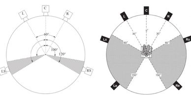
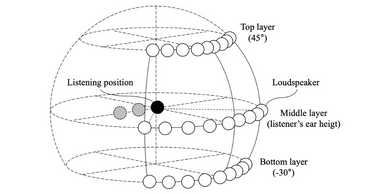
A good sound quality of a system is not only having a good balance in one channel, but also in all channels. The purpose of a sound system with more than one channel (stereo or multi-channel) is to reconstruct a sonic image and consequently create an immersive experience for the audience. We can see each channel as a single pixel of the image and utilize the “amplitude panning” principle for filling the gap between them. To make sure the sonic image is intact and non-distorted, the speaker configuration must be well designed. Indeed, a subjective evaluation experiment was conducted (ITU-R BS.2159-7) on loudspeaker configurations to investigate the degree to which the number and the angle of sound channels enhance the sensation of sonic image and sound source localization. But one must keep in mind that some sound systems, e.g., cinema sound, are also a PA ( public address) system which serves a large listening area. We must make a perfect balance between SPL coverage and sonic image reconstruction.